

Sales Department: 0086-532-87605018
After-sale Service: 0086-532-87660287
E-mail: export_sales@haitongyuanda.com
2023-03-22
Operating Procedure for Drilling Fluid Performance Test
Determination of Water Loss at High Temperature and High Pressure
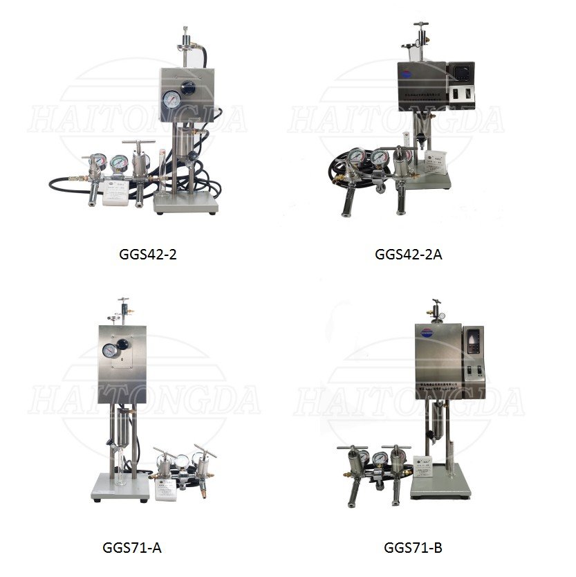
When the downhole liquid column pressure varies greatly from the formation pressure, the water loss situation varies greatly from the API water loss pressure. Due to the different formula of drilling fluid, its change law is also different. In order to understand the situation of water loss and mud cake of the close underground drilling fluid, it should be measured according to the actual situation of the well bottom (pressure difference pressure, temperature), which is actually difficult to achieve at present. Therefore, the drilling fluid is determined under the differential pressure of 3.5MPa and the bottom budget temperature. GGS-42(GGS42-2/GGS42-2A)and GGS-71(GGS71-A/GGS71-B) high temperature and high pressure water loss instrument are commonly used to measuring GGS-42 high temperature and high pressure water loss instrument when measuring temperature less than 150℃, and GGS-71 high temperature and high pressure water loss instrument when measuring temperature greater than 150℃.
1. Main Technical Indicators of the Instrument
1. Power supply: the voltage is 220V ± 5% (AC), and the frequency is 50Hz
2. Gas source: nitrogen, compressed air, etc., the rated pressure should be greater than 5MPa. Oxygen use is strictly prohibited.
3. Filter area: 22.6cm2.
4. Working pressure of the supercharger: 3.5MPa.
5. Working pressure of the return device: 0.7MPa.
7. Drilling fluid cup capacity: 176 ml
8. The capacity of the receiver (measuring cylinder) is 25 ml.
2. Operating Steps When the Temperature is Below or Equal to 150℃
1. Insert the thermometer into the thermometer jack of the heating sleeve, turn on the power supply, preheat to slightly above the required temperature (above 5~6℃), and adjust the constant temperature switch to maintain the required temperature.
2. Stir the drilling fluid to be tested at high speed for 10min, close the bottom valve stem, and pour the drilling fluid into the drilling fluid cup. Considering the expansion of the sample, make the liquid level at least 1.5cm from the top (on the engraved line), put the filter paper, cover the cup lid, and fix it with screws.
3. Close the upper and lower valve stems of the drilling fluid cup, put them into the heating sleeve, and insert the other thermometer into the socket of the upper thermometer of the drilling fluid cup.
4. Connect the high pressure filtrate receiver to the bottom stem and lock in place.
5. Connect the adjustable pressure source to the top stem and bottom receiver and lock in place.
6. Adjust the top and bottom pressure to 690 kPa (100 psi) when the upper and lower valve stems of the drilling fluid cup are closed. Open the top stem and apply the 690 kPa (100 psi) pressure to the drilling fluid. Maintain this pressure until the temperature reaches the required temperature and is constant, and the total heating time of the sample in the drilling fluid cup shall not exceed 1 hour.
7. When the sample temperature reaches the required temperature, adjust the top pressure to 4140 kPa (600 psi), open the bottom valve stem and record, collect the filtrate for 30min. The temperature shall be within ± 3℃ of the required temperature during the experiment. If the pressure in the filtrate receiver exceeds 690 kPa (100 psi) during the measurement, carefully release part of the filtrate from the filtrate receiver to reduce the pressure to 690 kPa (100 psi). Record the filtrate volume (in mL), pressure (in MPa), temperature, and time collected at 30min.
8. The filtrate volume should be corrected to the volume of the 45.8cm3 filtration area. If the filtrate area of the drilling cup is 22.6cm2, multiply the result by 2 to obtain the HF loss
9. After the test, close the top and lower valve stems, close the gas source and power supply, release the fold pressure from the pressure regulator and release the thimble.
Note: About 4140 kPa (600 psi) pressure remains in the drilling fluid cup.
10. Under the condition that the stems above and under the drilling fluid cup are closed and all pressure is dropped from the pressure regulator, remove the drilling fluid cup and keep it upright to room temperature (rinsing with water), remove the pressure in the inside of the cup, then open the drilling fluid cup, dump the drilling fluid, carefully remove the filter cake, and flush the floating mud on the surface of the filter cake with slow water flow.
11. Measure and record the thickness of the filter cake (unit in mm) and the quality of the filter cake (hard, soft, tough, loose, etc.). Wash and dry the pressure filter.
Note: The thickness of the mud cake is not multiplied by 2.
3. Determination of High Temperature and High Pressure Filter Loss with a Temperature Above 150℃
The measurement of high temperature and high pressure filter loss with temperature higher than 150℃ should check the use temperature and pressure of the instrument, and read the operation manual of the instrument in detail, otherwise accidents are easy to occur.
1. Insert the thermometer into the thermometer jack of the heating sleeve, turn on the power supply, preheat to slightly above the required temperature (above 5~6℃), and adjust the constant temperature switch to maintain the required temperature.
2. Stir the drilling fluid to be tested at high speed for 10min, close the bottom valve stem, and pour the drilling fluid into the drilling fluid cup. Considering the expansion of the sample, pay attention to make the liquid level at least 4.0cm away from the top, put the appropriate filter paper and filter screen, cover the cup lid, and fix it with screws.
3. Close the upper and lower valve stems of the drilling fluid cup, put them into the heating sleeve, and insert the other thermometer into the socket of the upper thermometer of the drilling fluid cup.
4. Connect the high pressure filtrate receiver to the bottom stem and lock it in place.
5. Connect the adjustable pressure source to the top stem and bottom receiver and lock it in place.
6. Apply the recommended backpressure to the top and bottom at the test temperature (see Table 1). Open the top valve stem and apply the same return force to the drilling fluid. Maintain this pressure until the temperature reaches the desired temperature and is constant. The total heating time of the samples in the drilling fluid cup shall not exceed 1 hour.
7. When the sample temperature reaches the desired temperature, increase the top pressure by 3450 kPa (500 psi) to the added back pressure, open the bottom valve stem and record. The temperature shall be kept within ± 3℃ and with appropriate pressure. If the return pressure in the filtrate receiver begins to rise during the measurement, be careful to release a small amount of the filtrate from the filtrate receiver to reduce the pressure., The filtrate was collected for 30min. The collected filtrate volume (in mL), pressure (in MPa),
8. After the measurement, close the top and bottom valve stems, close the gas source and power supply, and remove the pressure from the pressure regulator. In order to prevent evaporation, cool the filtrate for at least 5min, then carefully release the filtrate and record the total volume, and record the temperature, pressure and time. Make sure there is enough time for the filtrate to flow out from the receiver.
9. The filtrate volume should be corrected to the volume of the 45.8cm3 filtration area. If the filtrate area of the drilling cup is 22.6cm2, multiply the result by 2 to obtain the HF loss
Note: The pressure in the drilling fluid cup may reach 6500 kPa (950 psi), and shall remain upright and cool to room temperature before opening the drilling fluid cup (rinsing with water). Remove the pressure in the cup before opening it, otherwise, it may cause an accident.
10. Under the condition that the upper and lower stems of the drilling fluid cup are closed and the pressure has been released from the pressure regulator, remove the drilling fluid cup from the heating sleeve and keep it upright to room temperature (rinsing with water), open the valve stem, release the pressure in the cup, then open the drilling fluid cup, dump the drilling fluid, carefully remove the filter cake, flush the surface of the filter cake with slow water flow, and take special care of the protect the filter paper.
11. Measure and record the thickness of the filter cake (unit in mm) and the quality of the filter cake (hard, soft, tough, loose, etc.). Wash and dry the pressure filter.
Note: The thickness of the mud cake is not multiplied by 2.
4. Matters Need Attention
1. When dismantling and washing, the gas source must be cut off first, and all the residual pressure of the drilling fluid cup must be removed before being disassembled.
2. Do not pressure with oxygen and natural gas.
3. The instrument pipeline should be tested regularly to ensure safe use.
4. The heating and control system must be reliable, otherwise not used.
5. When the water loss is large, the filtrate should be put more times during the measurement.
Qingdao Haitongda Special Instrument Co.,Ltd.
Qingdao Haitongyuanda Special Instrument Co.,Ltd.
Tel Fax Registered Address | 0086-532-87605016/87605018 0086-532-87604773 No.320, Jiushui East Road,Licang district Qingdao City,Shandong Province,China |
Postal Address | No.10, Huaan Road,Chengyang district Qingdao City,Shandong Province,China |
Web | www.haitongda.com export_sales@haitongyuanda.com |