

Sales Department: 0086-532-87605018
After-sale Service: 0086-532-87660287
E-mail: export_sales@haitongyuanda.com
2023-03-21
Operating Procedure for Drilling Fluid Performance Test
Determination of Water, Oil, and Solid Phase Content
Drilling fluid solid phase meter is used to separate and determine the water, oil and solid phase volume in water-based drilling fluid samples. A known volume of water-based drilling fluid sample was heated in the stills to evaporate the liquid components, then condensed and collected in a graduated receiver. The liquid volume is determined directly from the reading of the oil and aqueous phases in the receiver. Total solid phase volume (suspended and dissolved) is obtained from the difference (total sample volume-liquid phase volume). Since any dissolved solid phase will remain in the stills, calculations must be done to determine the suspended solid phase volume. The relative volume of low specific gravity solid phase and weighted materials can also be calculated. Understanding solid phase concentration and composition is the basis for viscosity and water loss control of water-based drilling fluid.
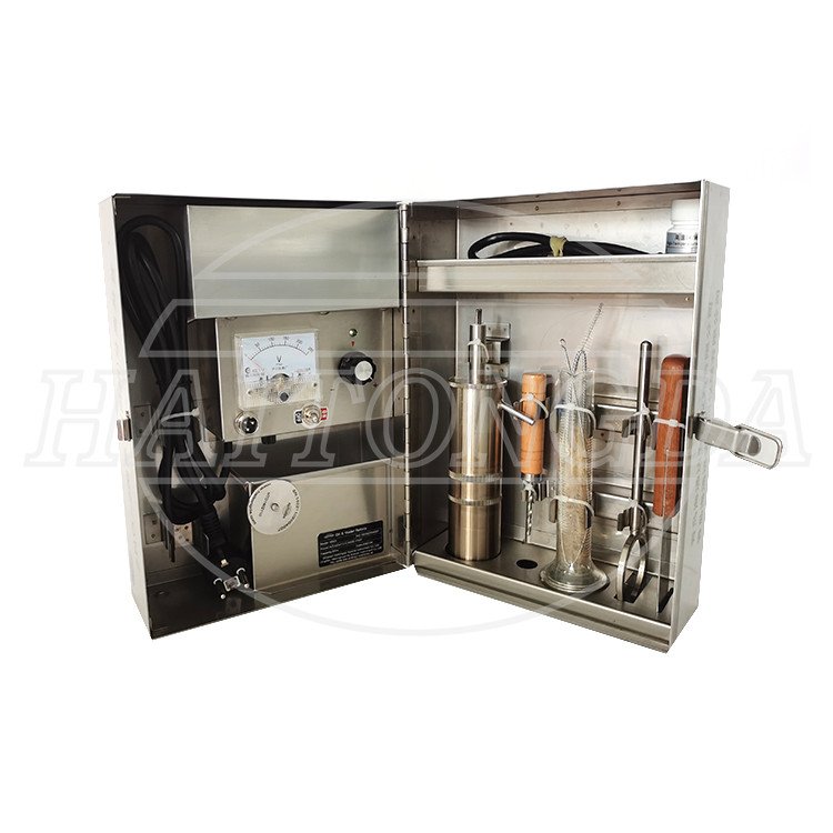
1. The Structure of the Instrument
1. Heating parts: with sufficient power to raise the sample temperature above the liquid phase evaporation temperature within 15min without causing the solid phase to overflow.
2. Sample cup: 20 mL or 10 mL;
3. Condenser: It has sufficient capacity to allow the oil and water vapor to cool to below the evaporation temperature before leaving the condenser.
4. Temperature controller: it can control the temperature of the stills within the range of 500℃± 40℃.
5. Liquid receiver: measuring cylinder or with scale test tube.
2. Determination Procedure
1. Make sure that the stills sample cup, condenser and liquid receiver are cleaned, dried and cooled after each use. Before each determination, the inside of the sample cup and the lid must be thoroughly cleaned. Or gently wipe the inside of the sample cup with wire wool. The condensing tubes were also cleaned with a tube brush and dried before each assay. The accumulation of some substances in the condensate tube may reduce the condensation efficiency and lead to incorrect liquid phase volume readings.
Note: The measurement used are different. See the manufacturer's instructions for complete measurement procedures.
2. Representative samples of water-based drilling fluid and cooled to approximately 26℃. The sample was passed through a horse funnel viscosity screen to remove plugging material, large drill chips or rock.
If the sample contains gas, 2 to 3 drops of defoaming agent should be added to about 30 mL sample and be slowly stirred for 2 to 3 min to remove these gases.
3. Apply a thin layer of silicone grease on the sample cup and the condenser thread. In this way, it can prevent the steam from dripping at the thread, and clean the instrument after the test.
4. Fill the defobamed drilling fluid sample with the distillation apparatus sample cup. Carefully cover the sample cup lid so that the excess drilling fluid overflows from the small holes on the lid to ensure that the sample volume in the sample cup is accurate. Cover the lid tightly and erase the sample cup and the outside of the lid. Ensure the silicone grease at the drilling fluid cup thread and the holes in the lid are not blocked. Gently remove the lid to scrape the sample attached to the lid face back into the sample cup.
5. Tighten the still sample cup to the upper sleeve, and finally tighten the heating rod to the still.
Insert the still drain into the side hole of the solid phase box and place the clean, dry tape liquid receiver under the condenser row outlet.
6. Heat it up and observe the liquid from the condensation drop. After not collecting any condensate, the heating was continued for 10min.
7. Cut off the power supply after the distillation. Observe whether there is solid material present in the liquid receiver, if the sample cup, the test must be repeated.
8. After the liquid is cooled to room temperature, read the volume of water and oil in the liquid receiver. Record the received
9. After cooling, remove and remove the stills, and scrape all the solid components in the cup and on the heating rod with a scraper.
10. After the test, wash the sample cups and measuring cylinders and keep them in a dry place.
3.Count
1. Volume percentage of water (%):
Vw = 100 (water volume) / (Sample volume)
Where: Vw water volume percentage.
2. Oil volume percentage (%):
Vo = 100 (oil volume) / (sample volume)
Where: Vo oil volume percentage.
3. Solid phase volume percentage (%):
Vs =100-(Vw +Vo )
Where: Vs solid phase volume percentage;
Vw water volume percentage;
Vo oil volume percentage.
4.Matters Need Attention
1. Before the end of distillation, the temperature controller indicator light is on to indicate the constant temperature, with no water drop out.
2. When the interface between oil and water is not clear, 2~3 drops of broken emulsion can be added to improve the liquid level clarity.
Qingdao Haitongda Special Instrument Co.,Ltd.
Qingdao Haitongyuanda Special Instrument Co.,Ltd.
Tel Fax Registered Address | 0086-532-87605016/87605018 0086-532-87604773 No.320, Jiushui East Road,Licang district Qingdao City,Shandong Province,China |
Postal Address | No.10, Huaan Road,Chengyang district Qingdao City,Shandong Province,China |
Web | www.haitongda.com export_sales@haitongyuanda.com |